- News & information
- About
- History
- George V. Voinovich
- George V. Voinovich Collection
- Calendar
- How to Find Us
- News
- Archives
- Photojournalism Fellowship Project
- Photo Essays
- Current Fellow
- Previous Fellows
- Reports and Publications
- Archives
- Students
- Prospective
- Center for Entrepreneurship
- Environmental Studies
- HTC/Voinovich School Scholars
- Master of Public Administration
- Current
- HTC/Voinovich School Scholars
- Center for Entrepreneurship
- Environmental Studies
- Master of Public Administration
- Alumni
- Contact
- School Leadership
- Strategic Partners Alliance
- Ohio University Public Affairs Advisory Committee
- Ohio University Public Affairs Advisory Committee
- Faculty and Fellows
- Faculty
- Visiting Professors
- Voinovich Fellows
- Professional Staff
An Approach to Solving Ordinary Differential Equations (I.Urieli, Winter 2002)
In many real life applications where we wish to evaluate a function, we are only able to define the relationship that the derivative of that function must satisfy. One example is the dynamics of a vehicle in which we wish to determine the velocity or acceleration, however the unknowns are specified only in terms of ordinary differential equations (ODEs) and initial conditions. In this note we wish to show one approach to the numerical solution of ODEs using MATLAB and the Classical fourth order Runge-Kutta method. This is a very personal approach and is somewhat different to that normally used, however I will try to justify it further on. The approach will be developed and illustrated in terms of two case studies.
Case Study 1 - a large angle pendulum
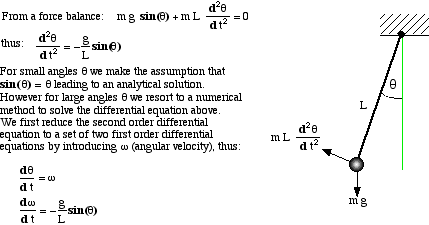
Consider a simple pendulum having length L, mass m and instantaneous angular displacement q (theta), as shown below:
Fortunately we can always reduce a n-th order ODE into a n-vector set of first order ODEs. Thus we need only concentrate on developing numerical techniques for solving first order ODEs. Processing vectors by computer simply requires looping sequentially through the indices of the vector, and MATLAB is particularly geared to this type of analysis.
Consider now the practical aspects of writing a function for evaluating this set of derivatives. One problem is that vectors are usually assigned generic names such as y for the set of dependent variables and dy for their derivatives, however we would like to retain their identity in terms of q (theta) and w (omega). This can be done by means of indices, as shown in the MATLAB function below:
   function

 [y,dy] = dpend(t,y)

   %Pendulum differential equations


   % G [m/s^2] acceleration due to gravity


   % LENGTH [m] pendulum length


   % Izzi Urieli - Jan 21, 2002


   global

 G LENGTH

  THETA = 1;
  % index of angle [radians]


  OMEGA = 2;
  % index of angular velocity [rads/sec]


  dy(THETA) = y(OMEGA);

  dy(OMEGA) = -(G/LENGTH)*sin(y(THETA));

  dy = [dy(THETA);dy(OMEGA)];
  % Column vector
Notice the use of upper case characters for both
the indices and the global variables, as is the convention in MATLAB.
Notice also that I am returning both y and dy (instead of only dy as
is normally done). This is because I find it convenient to load other
parameters on these vectors - again I will justify this in more
complex example following this case study.
Consider now a typical main function for this case study:
   %Solve the large angle pendulum problem


   % Izzi Urieli - Jan 21, 2002


  THETA = 1;
  % index of angle [radians]


  OMEGA = 2;
  % index of angular velocity [rads/sec]


   global

 G LENGTH

  G = 9.807;
  % [m/s/s} accel. due to gravity


  LENGTH = input(
  'Enter pendulum length [m] >'

 );

  angle0 = input(
  'Enter initial pendulum angle [degrees] >'

 );

  period = 2*pi*sqrt(LENGTH/G);

  fprintf('
  small angle period is %.3f seconds\n'

 ,period);

  tfinal = 2*period;

  n = input(
  'Enter the number of solution points >'

 );

  dt = tfinal/(n - 1);

  t = 0;

  y = [angle0*pi/180;0];
  % Initialise y as a Column vector


  time(1) = t;

  angle(1) = angle0;

   for

 i = 2:n

  [t, y, dy] = rk4(

   'dpend'


  ,2,t,dt,y);

  time(i) = t;

  angle(i) = y(THETA)*180/pi;

  fprintf('%10.3f%10.3f\n',time(i),angle(i));

   end


  plot(time,angle)
As with many MATLAB functions, this one is very
short and mostly self-documenting. Notice that after specifying the
system parameters we use the
for
loop to build the '
time
'
and '
angle
'
arrays in order to plot them. The most interesting aspect of this
program is the '
rk4
'
function call, to integrate one step '
dt
'
of the differential equation set given in function '
dpend
',
as follows:
 [t, y, dy] = rk4(
  'dpend'

 ,2,t,dt,y);
Thus the input arguments are the string constant representing the derivative function 'dpend', the number of differential equations in the set (2), the independent variable and increment ( t,dt ), and the dependent variable vector ( y ). The output arguments are the solution variables and derivatives ( t,y,dy ) integrated over one time step dt .
MATLAB provides five separate routines for solving ODEs of the form dy = f(x,y) where x is the independent variable and y and dy are the solution and derivative vectors. They are extremely simple to use, however they do not provide the versatility that I am looking for, including choosing the step size dx and overloading the y -vector (see case study following) so I decided to write my own routine. One of the most widely used of all the single step Runge-Kutta methods (which include the Euler and Modified Euler methods) is the so called 'Classical' fourth order method with Runge's coefficients. Being a fourth order method (equivalent in accuracy to including the first five terms of the Taylor series expansion of the solution) it requires four evaluations of the derivatives over each increment dx , denoted respectively by dy1 , dy2 , dy3 , dy4 . These are then weighted and summed in a very specific manner to obtain the final derivative dy .
   function

 [x, y, dy] = rk4(deriv,n,x,dx,y)

   %Classical fourth order Runge-Kutta method


   %Integrates n first order differential equations


   %dy(x,y) over interval x to x+dx


   %Izzi Urieli - Jan 21, 2002


  x0 = x;

  y0 = y;

  [y,dy1] = feval(deriv,x0,y);

   for

 i = 1:n

  y(i) = y0(i) + 0.5*dx*dy1(i);

   end


  xm = x0 + 0.5*dx;

  [y,dy2] = feval(deriv,xm,y);

   for

 i = 1:n

  y(i) = y0(i) + 0.5*dx*dy2(i);

   end


  [y,dy3] = feval(deriv,xm,y);

   for

 i = 1:n

  y(i) = y0(i) + dx*dy3(i);

   end


  x = x0 + dx;

  [y,dy] = feval(deriv,x,y);

   for

 i = 1:n

  dy(i) = (dy1(i) + 2*(dy2(i) + dy3(i)) + dy(i))/6;

  y(i) = y0(i) + dx*dy(i);

   end
The most interesting aspect of this function is the use of the MATLAB function ' feval ' to evaluate the function argument which is passed as a string. This is a fundamental aspect of MATLAB programming, and understanding this is essential to developing MATLAB programs.
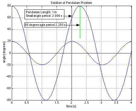
The plotting capabilities of MATLAB are extremely simple to use and very versatile. I show a typical output plot for the pendulum case study as follows:
We see that 20 degrees is about the limit of the small angle period (2.006 s), however at 80 degrees the period is seen to be much larger (2.293 s). This could only have been determined by numerically solving the differential equation set.
Case Study 2 - an electric bicycle
Since September 2001 I have been designing an electric bicycle (refer: www.eBiciBikes.com ). In this case study I would like to indicate how I am using the above method to do a dynamic simulation of the eBici bike in order to understand the behaviour of the vehicle under acceleration from a complete stop. Consider the main function as follows:
   %trialrun.m - of eBici


   % y(DIS) = distance covered (m)


   % y(VEL) = velocity (m/s)


   % y(POW) = instantaneous power (watts)


   % y(AMP) = motor current (amps)


   % Izzi Urieli - Jan 25, 2002


  DIS = 1;

  VEL = 2;

  POW = 3;

  AMP = 4;

   global

 VBAT SLOPE

  tfinal = 30;
  % (s) time span to integrate over


  VBAT = 36;
  % Volts


  SLOPE = 0;
  % Zero slope for this trial


  npoints = 100;
  % number of solution points


  dt = tfinal/(npoints - 1);

  t = 0;
  % Initialise independent variable time


  y = [0;0;0;0];
  % initial [dist;velo;power;amps]


  time(1) = t;

  dist(1) = y(DIS);

  velo(1) = y(VEL)*9/4;
  % meters/sec to mph


  power(1) = y(POW)/20;
  % watts/20 - for plot scale


  amps(1) = y(AMP);

   for

 i = 2:npoints

  [t, y, dy] = rk4(

   'deBici'


  ,2,t,dt,y);

  time(i) = t;

  dist(i) = y(DIS);

  velo(i) = y(VEL)*9/4;

  power(i) = y(POW)/20;

  amps(i) = y(AMP);

   end


  plot(time,velo,
  'k'

 )

  axis([0,30,0,40])

  grid on

  hold on

  plot(time,power,
  'r'

 )

  plot(time,amps,
  'b'

 )
Notice that there are
only two differential equations, velocity -
dy(DIS)
,
and acceleration -
dy(VEL)
,
however I have loaded the
y
-vector
with two more variables of interest, power -
y(POW)
,
and motor current -
y(AMP)
.
Since these values are evaluated within the derivative function
'
deBici
',
it is convenient to return them to the main function via the
y
-vector.
The function '
deBici
'
follows:
   function

 [y,dy] = deBici(t,y)

   %deBici - eBici differential equations of motion


   % y(DIS) = distance covered (m)


   % y(VEL) = velocity (m/s)


   % y(POW) = instantaneous power (watts)


   % y(AMP) = motor current (amps)


   % Izzi Urieli - Jan 21, 2002


  DIS = 1;

  VEL = 2;

  POW = 3;

  AMP = 4;

   global

 VBAT SLOPE

   % eBici basic parameters:


  mt = 100.0;

   % [kg] total mass of bike + rider


  mw = 1.0;

   % [kg] mass of each wheel


  rw = 0.2115;

   % [m] radius of wheel


  jw = mw*(rw^2);

   % [kg m^2] moment of inertia of each wheel (kg m^2)


   % equivalent inertial mass of bike + rider:


  mi = mt + 2*jw/(rw^2);

   % motor/generator mg62 specs:


  winding = 0.395;

   % [ohms] resistance


  kt = 0.62;

   % [Nm/A] torque constant


  imax = 32;

   % [amps] current limit setting on controller


   % wheel/motor gear ratio:


  n = 30/22;

   % wheel_torque / motor_torque


   % applied torque at rear wheel tw:


  tw = (n*kt/winding)*(VBAT - kt*n*y(VEL)/rw);

  twmax = n*kt*imax; % current limit setting on controller

   if


  tw > twmax % stall torque by current limit

  tw = twmax;

   end


   % current drain


  y(AMP) = tw/(n*kt);

   % mechanical power (force*velocity (watts)):


  y(POW) = (tw/rw)*y(VEL);

   % resistive forces: drag, slope, rolling resistance


  cda = 0.4;

   % [m^2] coef. of drag * frontal area


  density = 1.18;

   % [kg/m^3] air density


  drag = cda*density*y(2).^2/2;

  cr = 0.005;

   % coefficient of rolling resistance


  g = 9.807;

   % [m/s^2] gravity


  resist = mt*g*(cr + SLOPE);

  dy(DIS) = y(VEL);

   % velocity


  dy(VEL) = (tw/rw - (drag + resist))/mi;

   % acceleration


  dy = [dy(DIS); dy(VEL)];

   % must be a column vector
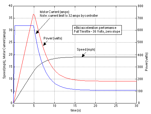
The ability to load the y -vector with the motor current and power values allowed me to develop the following transient performance plot from the main function:
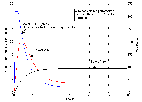
Note that if we wanted to limit the speed to below 10 mph then all that we would to do is reduce the battery voltage from 36 volts to 18 volts. This is because the back emf (induced voltage) of a permanent magnet motor is linearly proportional to the motor rotational speed. Thus the following plot results:
Contact Information:
(740) 593–9381 | Building 21, The Ridges
Ohio University Contact Information:
Ohio University | Athens OH 45701 | 740.593.1000 ADA Compliance | © 2018 Ohio University . All rights reserved.


