- News & information
- About
- History
- George V. Voinovich
- George V. Voinovich Collection
- Calendar
- How to Find Us
- News
- Archives
- Photojournalism Fellowship Project
- Photo Essays
- Current Fellow
- Previous Fellows
- Reports and Publications
- Archives
- Students
- Prospective
- Center for Entrepreneurship
- Environmental Studies
- HTC/Voinovich School Scholars
- Master of Public Administration
- Current
- HTC/Voinovich School Scholars
- Center for Entrepreneurship
- Environmental Studies
- Master of Public Administration
- Alumni
- Contact
- School Leadership
- Strategic Partners Alliance
- Ohio University Public Affairs Advisory Committee
- Ohio University Public Affairs Advisory Committee
- Faculty and Fellows
- Faculty
- Visiting Professors
- Voinovich Fellows
- Professional Staff
Chapter 10: Air - Water Vapor Mixtures
a) Humidity and the Adiabatic Saturation Process
Atmospheric air includes dry air and water vapor . Recall that for an ideal gas, enthalpy (h) is a function of temperature only (Δh = C P .ΔT). Notice also from the h-s diagram for steam that at relatively low temperatures (<60°C) the water vapor in the air has a constant enthalpy at constant temperature from saturated vapor through the superheated region, thus can be treated as an ideal gas.
From Dalton's Law of Partial Pressures we have for a dry-air/water-vapor mixture that the total pressure P is given by:
P = P a + P v
where subscript a refers to the dry air, and v to the water vapor.
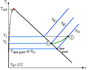
We find it convenient to sketch our processes for the water-vapor component on a T-v diagram (which we prefer to the ubiquitous T-s diagram in common use, since entropy is not considered in this Section)
Consider the water vapor shown at state (1) on the diagram. We will find it convenient throughout this section to evaluate enthalpy with respect to T 0 = 0°C, since ultimately we only consider differences in enthalpy. From the above diagram:
h v@T = h g@T
where g refers to the saturated vapor state.
Note that h g@T can be obtained from the saturated vapor tables, or one can use Izzi's method, which has a maximum error of 0.5% at 60°C:
We also evaluate the enthalpy of the dry air component with respect to T 0 = 0°C, thus:
since at the temperatures under consideration C P is approximately 1.00 [kJ/kg°C].
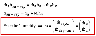
In order to evaluate the enthalpy of the atmospheric air we need to first find the mass flow rates of both the dry air and the vapor. We always evaluate these with respect to the mass flow rate of the dry air, and this in turn leads us to the definition of Specific Humidity ω, as follows:
Note that other terms in common usage are humidity ratio or absolute humidity to denote specific humidity. The specific humidity can be conveniently determined in terms of the partial pressures P a and P v as follows:
Referring to the T-v diagram above, we now define Relative Humidity φ as follows:
Furthermore, we can determine the specific humidity in terms of the relative humidity, and vice versa, as follows:
The Adiabatic Saturation Process
There is no direct method of measuring specific humidity ω or relative humidity φ thus in this section we develop the Adiabatic Saturation Process leading to the practical Wet & Dry Bulb Thermometer , or Sling Psychrometer . Consider the channel below in which air of unknown humidity enters at station (1) and after absorbing moisture from the liquid pool, exits at 100% relative humidity at station (2). This process is shown on the T-v diagram below.
mass flow:
energy:
Referring to the T-v diagram above, since φ 2 =100%, P v2 =P g2 , thus:
In order to determine T 2 and T 1 we use a wet & dry bulb thermometer (or sling psychrometer ), typically as in the following figure (refer: Sling Psychrometer Demonstration ). The wet bulb is wrapped in a cotton wick saturated with water, and one swings the thermometer in the air until a steady temperature is attained. The wet bulb temperature T wb is then very closely equal to the adiabatic saturation temperature T 2 .
Note that the relative humidity is then determined by means of a slide-rule on the handle of the sling-psychrometer, as shown in the above diagram.
On to Section b) - The
Psychrometric Chart


Engineering Thermodynamics by Israel
Urieli
is licensed under a Creative
Commons Attribution-Noncommercial-Share Alike 3.0 United States
License
Contact Information:
(740) 593–9381 | Building 21, The Ridges
Ohio University Contact Information:
Ohio University | Athens OH 45701 | 740.593.1000 ADA Compliance | © 2018 Ohio University . All rights reserved.


