- News & information
- About
- History
- George V. Voinovich
- George V. Voinovich Collection
- Calendar
- How to Find Us
- News
- Archives
- Photojournalism Fellowship Project
- Photo Essays
- Current Fellow
- Previous Fellows
- Reports and Publications
- Archives
- Students
- Prospective
- Center for Entrepreneurship
- Environmental Studies
- HTC/Voinovich School Scholars
- Master of Public Administration
- Current
- HTC/Voinovich School Scholars
- Center for Entrepreneurship
- Environmental Studies
- Master of Public Administration
- Alumni
- Contact
- School Leadership
- Strategic Partners Alliance
- Ohio University Public Affairs Advisory Committee
- Ohio University Public Affairs Advisory Committee
- Faculty and Fellows
- Faculty
- Visiting Professors
- Voinovich Fellows
- Professional Staff
User Tools
Table of Contents
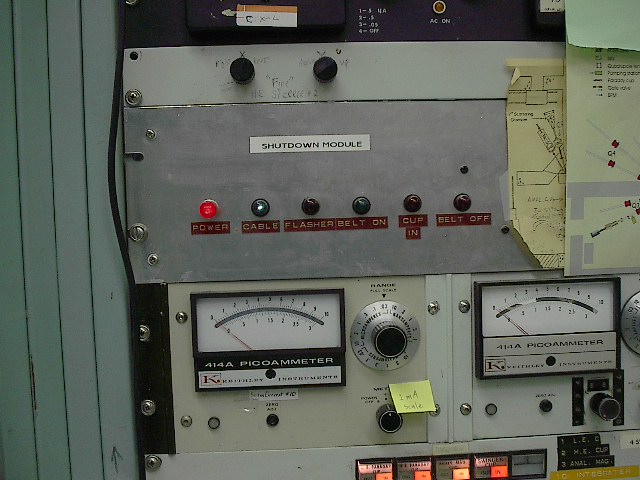
Shutdown Module: Located above beam current meters.
This is the actual device that shuts down the accelerator, and sounds an alarm, when it receives a shutdown command from a connected device. There are two devices that provide a shutdown command to this module; the Radiation Monitor System and the E2 alarm panel when in “connect” mode. When a shutdown command is received this module:
- 1) Turns off the Pelletron Power Center in the Vault causing the chains and upcharge power supplies to go off. The Pelletron Power Center also disables control power for all electrostatic devices on the control console.
- 2) Sounds an audible alarm. (abrasive, pulsating sound)
- 3) De-energizes the LE faraday cup causing the cup to goto the “IN” position.
The module is also responsible for controlling the flashing red warning lights and start up claxon. When it senses a chain start it activates the flashing red light circuit and sounds the claxon for 5 seconds. When it senses that the chains are off it deactivates the flashing red light circuit.
The lights on the front of the module are:
- 1) Power: Indicates the module is receiving 115V
- 2) Cable: Indicates that the cable connecting the Radiation Monitor to the shutdown module is intact.
- 3) Flasher: Indicates that the flashing red light circuit is active.
- 4) Belt On: Indicates that a chain start has been detected and chains are running.
- 5) Cup In: Indicates that LE cup in relay has activated.
- 6) Belt Off: Indicates that the Pelletron power center OFF relay has activated.
ACTIONS:In order to reset a shutdown alarm condition the operator must:
- first clear the condition that caused one of the connected devices to request a shutdown.
- Proceed to the back of the cabinet and press the RESET button on the back of the module. There is also a TEST button on the back of the module that will create a shutdown request. Press the RESET button to end the test.
NOTE:There is a backup shutdown module. When it activates due to radiation rate the “Rad. Mon.” light will be illuminated on the Emergency Off Annunciator Panel as long as the radiation is above the rate shutdown threshold. This module does not activate the audible alarm. On rare occasions when the radiation being produced is exactly at the rate threshold, this module can activate a shutdown before the main module.
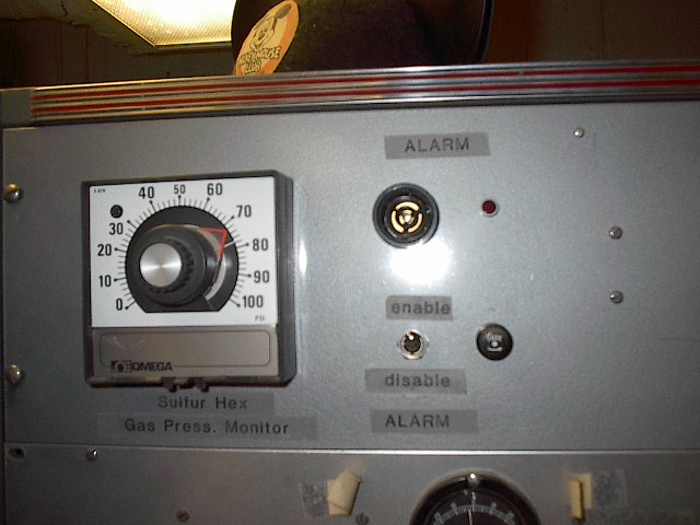
SF6 Alarm Panel: Located above the accelerator console.
This system receives data from a pressure transducer on the accelerator tank. The dial has two functions. The white line indicates the measured tank pressure as reported by the transducer. The orange pointer is connected to the knob on the front of the dial and its position sets the alarm activation threshold. There is some deadband around the threshold. When the white line falls below the alarm threshold the red light next to the speaker will illuminate, and the speaker will produce a high pitched beeping sound. The enable/disable switch allows the user to silence the speaker when in alarm, but only a change in the orange pointer will clear an alarm condition. It is possible for this alarm to activate when the accelerator has been idle for an extended time and cools enough for the pressure to fall below threshold.
ACTIONS:An operator who finds an SF6 alarm active should look at the Tank Volume plot in the data logging system (this plot should be a flat line if there is no leak)and the oxygen levels in the pit as reported by the VESDA fire alarm system to help determine if the alarm is valid or not.
- If both conditions are normal the threshold may be reset and the event noted in the Accelerator Logbook.
- If oxygen levels in the pit or on the dock get dangerously low the VESDA computer will play warning messages, text/email staff, and generate a Supervisory Trouble on the fire alarm system. You must contact accelerator staff - you may be instructed to activate the fire alarm for building evacuation. If not sure about Tank Volume or VESDA data, contact accelerator staff for further evaluation.
Radiation Monitor:
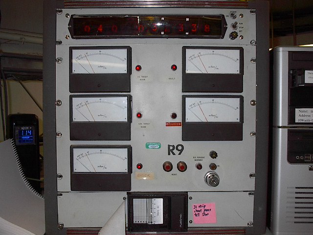
The Radiation Monitor processes signals from the fixed detectors throughout the facility. The radiation reported by any one detector will be counted if the door for that detector is not secured. Only the largest unsecured radiation level is counted. The Vault detector is secured by closing the Vault gate, the large and small target room detectors are secured by closing the doors to those rooms. The Dock detector always counts regardless of the position of the large door between the Swinger and the Dock. The Source detector is never secured and never counted, it is informational only, however, it will activate warning signs in the source area at acertain level (see Source Radiation Warning section). The Radiation Monitor has door status lights next to the meter for the area, a red light means that the door is not secure.
The digital display across the top has two functions. The three digits on the left are the cumulative dose, in counts, collected by the unsecured detectors. This value resets to zero every 24 hours. The cumulative dose is also tracked by the strip chart recorder at the bottom of the unit, and is also recorded by the data logging system, and resets to zero every 8 hours. The six digits on the right are the clock in 12 hour time. It should reflect the approximate time, and the accumulated dose should be resetting at midnight, 8am, and 4 pm. The toggle switch to the right of the digital display should normally be in the run position to count time. The Stop and Set positions are used when adjusting the clock time and the 8 and 24 hour reset point.
The Radiation Monitor has an audible warning alarm, it produces a steady, high pitched whistle. This alarm will sound when there is a power supply failure on one of the detectors, or when the accumulated dose has reached 80% of the maximum dose allowed in an 8 hour shift. The latter situation will also illuminate the 80% warning light on the front of the unit. The audible alarm for the 80% warning will silence after about 30 seconds but the light will remain on. The audible alarm for a power supply failure will sound until the problem is fixed. An 80% warning should cause the operator to pause the experiment and consult with the Radiation Safety Officer, or accelerator staff, to study the situation and modify operations in order to prevent a shutdown on accumulated counts.
There are two conditions which will cause the Radiation Monitor to send a shutdown request to the Shutdown Module.
The first is based on instantaneousrate. A rate greater than 100 mRem/hr on an unsecured detector will cause this type of shutdown.
Actions:Once the operator has verified that no individual was exposed and the situation has been corrected, the operator may silence the shutdown alarm and resume operations. The event shall be recorded on the “Accidental Shutdown Log” (form found in Testing, Calibration, and Shutdown book) and in the electronic log book.
The second condition is based on accumulated counts. Reaching 200 counts (20 mrem) in an 8 hour cycle will cause this type of shutdown.
Actions:Two persons are required to reset the Radiation Monitor from an accumulated dose shutdown, one has to press the T3 button in the rear, the other has to press the two buttons on the front. A full written explanation shall be completed and added to the Health Physics Daily Log Book. The event shall be recorded in the “Accidental Shutdown Log” (form found in Testing, Calibration, and Shutdown book) and the electronic log book.The Radiation Monitor shall never be reset unless there is absolute assurance that no personnel has received the dose registered on the digital counter. An investigation shall be made, documented, and action taken to prevent recurrence of this type of shutdown.
Alarm Panels E1 and E2:
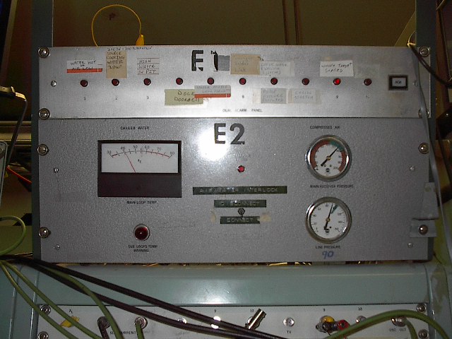
Panel E2 monitors the chilled water and compressed air systems, both of which are critical to accelerator operations. The Air/Water Interlock switch in the middle allows the panel to be connected to the Shutdown Module so that an alarm condition will shutdown the accelerator. This is the normal configuration. When in Disconnect mode, the alarm will still sound but the accelerator will not be shutdown.
The Compressed Air Main Receiver Pressure is the pressure in a storage tank that periodically gets refilled by the main compressor. This pressure should always be in the green zone on the dial, or slightly above. This pressure is also recorded by the electronic data logging system and cycles up and down as the compressor runs. The line pressure is regulated to 90 psi after the Main Receiver and is the air pressure in the building. A line pressure below 90 psi will cause an E2 alarm. The Main Loop Temp meter is the temperature of the main chilled water loop coming from the chiller on the roof. This temperature is recorded by the electronic data logging system and cycles up and down as the chiller runs. If this temperature gets too high the E2 alarm will activate. The Sub Loop Temp warning light will activate and cause an E2 alarm if the temperature of any of the 4 sub loops (the pumps in the Vault) becomes too hot. The red light in the middle of Panel E2 will light when any one of the alarm conditions exists. It is up to the operator to determine which of the conditions is outside of normal parameters.
Panel E1 monitors less critical conditions and provides the audible alarm for both Panels E1 and E2. A row of red lights across the panel indicate which alarm is active by blinking the red light for that alarm and sounding the audible alarm. The audible alarm is a rapidly oscillating high-low tone. The audible alarm may be silenced by pressing the “ACK” button to acknowledge the alarm. If the alarm condition is still present, the red light for that alarm will become steadily lit after the ACK button is pushed. If the alarm condition was brief and is no longer present, the red light for that alarm will go out when the ACK button is pushed.
Actions:The operator must note which alarm light(s) was flashing prior to pressing the ACK button. The E1 alarms are as follows:
- 1) Water Hot or Air Low. This alarm activates when Panel E2 detects an alarm condition. If E2 is in “Connect” mode the accelerator will shut down. The operator must turn down all magnets and contact a staff member. If, for some reason, the accelerator does not shut down, the operator should also turn off the accelerator in the normal fashion.
- 2) Source Cooling Water Low. The sources are cooled by an independent water loop circulating high resistivity de-ionized water. If the water in the loop gets below a certain level the alarm will sound even though water is still circulating. This alarm tends to go on and off repeatedly when the water is right at the alarm level. Make a logbook entry and contact staff the make arrangements for adding water to the loop.
- 3) High Water In Pit. The pit below the accelerator is the lowest point in the building and water collects there. The water is normally removed by a sump pump. If this pump fails the pit will fill with water. When this alarm is active the operator must go to the Vault and look down in the pit for the presence of water. If water is present contact staff immediately. If no water is present make a logbook entry and contact staff so that the alarm may be reset at first opportunity.
- 4) Dock Doorbell. Self explanatory.
- 5) Sputter Source Low Flow. There is a flow switch on the water loop cooling the sputter source. This alarm will activate if the water flow becomes too low or stops. If this alarm activates begin to shut down the source and contact staff. If this alarm activates in conjunction with the Source Cooling Water Low alarm there is likely a water leak in the source area - shutdown both sources and contact staff immediately.
- 6) Swinger Solder Link. There is a switch on the swinger that will activate when a gas cell fails and cause this alarm. When a gas cell is not in use this switch must be set so as not to be in the alarm position. This alarm will also cause the swinger gate valve to close and prevent the gate valve from opening as long as the alarm condition is true.
- 7) Phase Failure Detected. This alarm will activate if any one of the electrical phases serving the building is interrupted for half a second or longer. The operator will need to execute the brief or extended power outage procedures as the case may be.
- 8) Chain Stretch. This alarm will activate when the Pelletron chains have stretched to the point that motor assemblies are about ¼ inch from bottoming out on the column base plate. When this alarm sounds the operator needs to make an electronic logbook entry and email it to everyone so that a tank entry may be scheduled soon to shorten the chains.This alarm will definitely happen at accelerator startup. It is not clear whether this alarm will go out or stay on once the chains are running at full speed.
- 9)And (10): For temporary use. Connected to the BNC connectors on the console patch panel labeled E1 alarm 9, 10. Contact closure will activate the alarm.
Pelletron AC Power Center: Located in the Vault by the sputter source gate.
This unit controls the chain drive motors and upcharge power supplies. It also provides control power to all the electrostatic devices on the control console. It is normally energized as indicated by the red Power On light on the front door. A shutdown command from the Shutdown Module will cause this unit to go into a power off mode, disabling the chain drive motors and upcharge power supplies. This unit also goes into the power off mode when either or both of the tube vacuums goes bad, or one of the Emergency Off buttons in the lab has been pushed. Bad vacuum and Emergency Off events do not cause any type of alarm to activate. When this unit is off, the green ”Interlocks OK” light on the charging controller will not be illuminated in the control room, accelerator control power will be off, and all electrostatic common beam line components will be de-energized.
Actions:
- Reconfigure the TPS and CHARGING CONTROLS as directed in the Accelerator Shutdown procedure.
- The operator will have to press the “ON” button to re-energize the unit only after a shutdown command, bad vacuum event, or Emergency Off event has been cleared and corrected.See the appropriate instructions to clear the condition.
- Be aware that the Beam Warning system may activate when power is restored.
Emergency Off Button (EMO) Reset:
Actions:
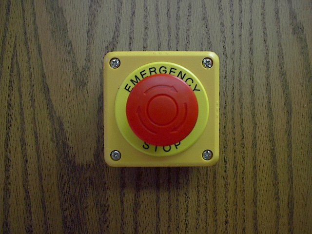
- Identify which EMO was pushed (see the Emergency Off Annunciator Panel) and investigate the situation that led to the Emergency Stop event.
- Follow Section VIII of the Radiation Safety Handbook if there was any possibility of exposure.
- Otherwise, provide a detailed written account of the event in the Electronic Logbook. Describe who was involved, which button was pushed, why it was pushed, and describe the course of events thast led to the Emergency Stop.
- Reconfigure the TPS and CHARGING CONTROLS as directed in the Accelerator Shutdown procedure.
- Reset the activated EMO. Turn the red knob in the direction indicated by the arrows. The knob will pop outwards when it releases.
- Go to the Vault and reset the Pelletron AC Power Center. You may hear faraday cups operate when you do this.
- Go to the Control Room and place all faraday cups in the “IN” position.
- Follow the Accelerator Startup Procedure and resume operations.
Beam Warning System
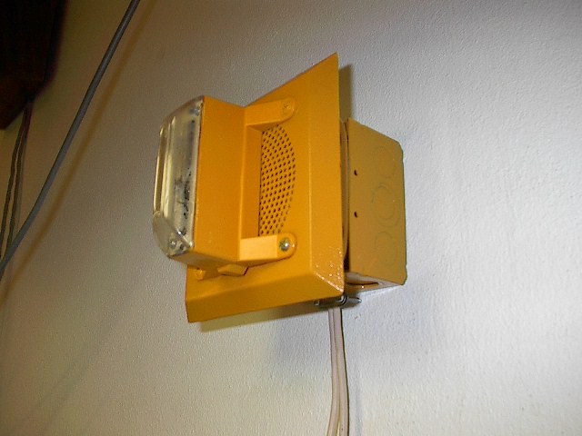
All areas that will experience high radiation levels, when beam and target conditions lead to such levels, are equiped with an audible and visual warning system which will activate for 15 seconds when the Low Energy Faraday Cup is lifted to inject beam into the Accelerator. The 15 second warning system activation will operate every time the LE cup is commanded to the OUT position, independent of whether or not the beam and target conditions will produce detectable radiation. The warning devices consist of a yellow speaker housing with a blue strobe light across the front. The audible warning will be variable, but always distinctly different from all other audible alarm and warning sounds in the building.
High Radiation Mode:
A “HIGH RAD MODE” switch is located on the Faraday Cup Control Module. When this switch is in the “OFF” position the LE cup will lift instantaneously and the audible and visual warning will be active for 15 seconds. When this switch is in the “ON” position there will be a 15 second delay between pushing the LE Cup “OUT” button and the actual lifting of the LE Cup, as well as the 15 second audible/visual warning.
The Operator shall place the HIGH RAD MODE switch in the “ON” position when:
- The experiment conditions are known to produce measurable radiation
- Any time measurable radiation appears on any of the fixed monitors
- Any time there is uncertainty in the radiation that will result from the experiment conditions
The Operator may place the HIGH RAD MODE switch in the “OFF” position when:
- The experiment conditions are known to NOT produce measurable radiation
- When an experiment is tuned and running and no radiation has been detected in any of the fixed monitors.
Tritium Exhaust Fans
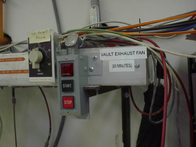
Both the Large Target Room and the Vault are equipped with large exhaust fans. These fans draw air from the rooms and discharge it inside the fenced area on the roof. These fans are intended to be used in a tritium emergency but may also be used anytime there is a need to purge air from these rooms.
The Large Target Room fan is activated by turning the dial in the control room. The dial is a timer and the fan will run for the time selected, up to 60 minutes, and then shut off.
The Vault fan is activated by pushing the “START” button. The run time is fixed to be 60 minutes. The air handler in the Vault will turn off while the exhaust fan is running and turn back on when the fan goes off. Pushing the “STOP” button will turn off the fan at any time during the 60 minute run cycle.
Tritium Monitor:
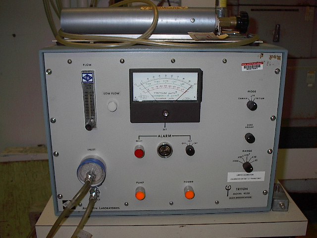
The Tritium monitor samples the air for tritium using an air pump, and ionization chambers. Air samples are taken from the area where tritium operations are now or have been carried out. There is a connection board above the tritium monitor to show if the sampling is being done in the large target room or the swinger. Tritium Monitor detection system consists of two ionization chambers. One ion chamber is used for flowing through the air sample and the second is used for compensation of the background.
The Tritium monitor is normally left on the x1 scale with the alarm level set at the maximum of the range (~10 microcuries/meters3). The maximum allowable level is 20 microcuries/meters3.
Actions if the Tritium monitor is alarming:
-Check that there is air flow through the ion chamber. The Tritium Monitor will alarm if the pump is not on
-If the level of tritium is greater than 20 microcuries/meters^3, evacuate the area (large target room or vault) and turn the exhaust fans for the area on.
-Contact the people on the Tritium Emergency Check list posted in the Control Room (or an operator with a tritium endorsement) if this alarm is not caused by too little air flow or immediately following a power blink or outage.
Source Radiation Warnings
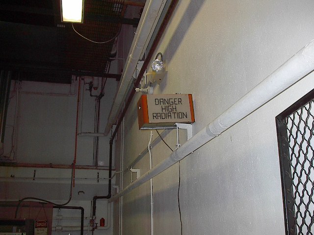
There is an unmoderated (no polyethylene) fixed monitor next to the Accelerator tank. This monitor appears on the Radiation Monitor System as the “SOURCE” detector. This detector is meant to pick up gamma or x-ray radiation resulting from source activity, or more likely, from carbon foil contamination activity in one of the Accelerator Tubes. It can also be expected to register when there is a high level of activity due to running on the Swinger. When the detector reaches 10 mRem/hr, it will activate the radiation warning signs on each side of the source area.
Page Tools
Contact Information:
(740) 593–9381 | Building 21, The Ridges
Ohio University Contact Information:
Ohio University | Athens OH 45701 | 740.593.1000 ADA Compliance | © 2018 Ohio University . All rights reserved.


