- News & information
- About
- History
- George V. Voinovich
- George V. Voinovich Collection
- Calendar
- How to Find Us
- News
- Archives
- Photojournalism Fellowship Project
- Photo Essays
- Current Fellow
- Previous Fellows
- Reports and Publications
- Archives
- Students
- Prospective
- Center for Entrepreneurship
- Environmental Studies
- HTC/Voinovich School Scholars
- Master of Public Administration
- Current
- HTC/Voinovich School Scholars
- Center for Entrepreneurship
- Environmental Studies
- Master of Public Administration
- Alumni
- Contact
- School Leadership
- Strategic Partners Alliance
- Ohio University Public Affairs Advisory Committee
- Ohio University Public Affairs Advisory Committee
- Faculty and Fellows
- Faculty
- Visiting Professors
- Voinovich Fellows
- Professional Staff
Chapter 6: Entropy - a New Property
b) Aircraft Gas Turbine Engines
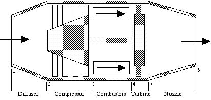
There are many different forms and modifications of aircraft gas turbine engines, and in this course we discuss two variants - the ideal turbojet engine, and the gas turbine engine for usage in helicopters.
The ideal turbojet engine shown schematically in the above figure comprises the series connection of five components - diffuser, compressor, combustor, turbine, and nozzle. The analysis of the complete system, is best done in terms of the h-s (enthalpy-entropy) diagram, which we will develop in class. Throughout the system we assume that the fluid is pure air, and the combustors are considered to be constant-pressure heat-addition devices. Notice that the sole purpose of the turbine is to drive the compressor, the nozzle providing the final kinetic energy increase to drive the aircraft.
The gas turbine engine for usage in helicopters is shown below:
In this case we see that there is no diffuser or nozzle, and that the turbine section has been replaced by two independent turbines - a "gas generator", or "gassifier" turbine to drive the compressor, and an output turbine to drive the helicopter blades. A typical gas turbine engine of this type is the General Electric T700 engine shown below, which is used in the Army Black Hawk helicopter.


The Industrial Technology department retains a fullsize cutaway model of a T700 engine, which is the basis of the following solved problem.
Solved Problem 6.11 - The General Electric T700 Gas Turbine Engine
Problem 6.12 - Actual Power Output of the T700 Gas Turbine Engine
Solved Problem 6.13 - T700 Proposed Turbojet Conversion
Problem 6.14 - An Aircraft Gas Generator Turbine

Engineering Thermodynamics by Israel
Urieli
is licensed under a Creative
Commons Attribution-Noncommercial-Share Alike 3.0 United States
License
Contact Information:
(740) 593–9381 | Building 21, The Ridges
Ohio University Contact Information:
Ohio University | Athens OH 45701 | 740.593.1000 ADA Compliance | © 2018 Ohio University . All rights reserved.


