
Solved Problem 6.11 - The General Electric T700 Gas Turbine Engine
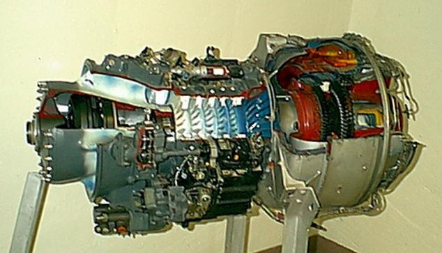
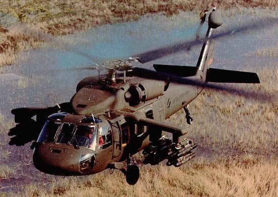
We wish to do an ideal thermodynamic analysis of the General Electric T700 gas turbine engine, which is used to power the Army Black Hawk helicopter . Consider the schematic diagram of the engine shown in the figure below:

Notice that there are two turbines operating on independent output shafts. The High Pressure (first) turbine, named the Gas Generator Turbine , is directly connected by a shaft to the compressor. Its sole purpose is to drive the the axial/centrifugal compressor , thus the energy output of this turbine must equal the energy consumed by the compressor. The Low Pressure (second) turbine, named the Power Turbine , is connected via gearing to the helicopter rotor.
![]() Problem
6.11
- Assume that the compressor and both
turbines are isentropic, and that the combustion process occurs at
constant pressure (isobaric). Using the information shown on the
schematic diagram above, do the following:
Problem
6.11
- Assume that the compressor and both
turbines are isentropic, and that the combustion process occurs at
constant pressure (isobaric). Using the information shown on the
schematic diagram above, do the following:
-
a) Sketch the entire process on an h-s diagram, clearly showing the 5 stations on the diagram and the relevant isentropic and constant pressure lines.
-
b) determine the energy consumed by the compressor [w C = -328kJ/kg] , and the temperature at the outlet of the compressor [T 2 = 587K] .
-
c) determine the heat energy absorbed by the working gas in the combustion chamber [q H = 754kJ/kg] .
-
d) determine the temperature [T 4 = 975K] and the pressure [P 4 = 546kPa] at the outlet of the gas generator turbine.
-
e) determine the temperature [T 5 = 627K] and energy output of the power turbine [w PT = 382.5kJ/kg] .
-
f) given that the mass flow rate of the working gas through the system is 4.6 kg/s, determine the power output of the power turbine [1.76MW] .
(Data obtained through private communication with Dr. Tom Scott )
Note: Because of the large temperature variation throughout this problem we will need to consider the temperature dependence of the Specific Heat Capacities of Air . All thermo texts that we know of present a method of doing this using the tabulated function s 0 , relative pressure P r , and relative specific volume v r . We prefer the simpler approach of using a constant specific heat capacity C P and ratio of specific heats k, where the values are chosen at the average system temperature. This has always provided an answer within around 1% accuracy. In the above schematic diagram we see that the temperature extremes of the system are 16°C - 1000°C (289 K - 1273 K), giving an average temperature of 781 K. From the table of Specific Heat Capacities of Air we see that at 800 K, C P = 1.099 [kJ/kg.K] and the ratio of specific heat capacities k = 1.354, thus we use those values throughout this problem.
Solution Approach:
-
a) Sketch the entire process on an h-s diagram, clearly showing the 5 stations on the diagram and the relevant isentropic and constant pressure lines.
Unlike the case with a pure fluid such as steam the h-s diagram is not drawn to scale, however is sketched in order to provide an intuitive graphical understanding of the problem. Furthermore, for an ideal gas the enthalpy is proportional to the temperature, hence the y-axis can be considered either an enthalpy or temperature axis. The various temperatures and pressures shown on this diagram are evaluated and plotted as we progress with the solution.
Notice that the various temperatures and pressures shown on this diagram are evaluated and plotted as we progress with the solution.

-
b) determine the energy consumed by the compressor (w C - kJ/kg), and the temperature at the outlet of the compressor (T 2 ).
Ideally both the compressor and the turbine are isentropic devices, thus given the pressure ratio, in order to determine the temperature we consider the isentropic relations developed for an ideal gas.

-
c) determine the heat energy absorbed by the working gas in the combustion chamber (q H - kJ/kg).

-
d) determine the temperature (T 4 ) and the pressure (P 4 ) at the outlet of the gas generator turbine.
Once more. since both turbines are isentropic, we use the pressure temperature relations developed for an isentropic process of an ideal gas.

-
e) determine the temperature (T 5 ) and energy output of the power turbine (w PT - kJ/kg).

-
f) given that the mass flow rate of the working gas through the system is 4.6 kg/s, determine the power output of the power turbine (MW).
Note that the actual power output of the T700 engine is around 1800 hp, which is significantly less than the above value. This is because we have assumed that the compressor and both turbines are isentropic, which will never occur in practice. Problem 6.12 is an extension to this exercise in which we consider non-isentropic compressor and turbines.